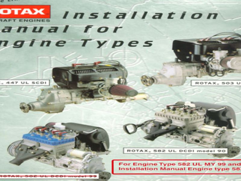
Congratulation on your decision to use a ROTAX® aircraft engine. Before starting with the engine installation, read this Installation Manual carefully. The Manual will provide you with basic information on correct engine installation, a requirement for safe engine operation. If any passages of the Manual are not completely understood or in case of questions, please, contact an authorized Distribution- or Service Partner for ROTAX ® engines.
Remarks
This Installation Manual is to familiarize the owner/user of this aircraft engine with basic installation instructions and safety information. For more detailed information on operation, maintenance, safety or flight, consult the documentation provided by the aircraft builder and dealer. For further information on maintenance and spare part service contact the nearest ROTAX ® distributor (see chapter of Service Partners)
Engine serial number
On all enquiries or spare parts orders, always indicate the engine serial number, as the manufacturer makes modifications to the engine for further development. The engine serial number is on the top of the crankcase, magneto side, or ignition cover.
Although the mere reading of such an instruction does not eliminate a hazard, the understanding and application of the information will promote correct use. The information and components-/system descriptions contained in this Maintenance Manual are correct at the time of publication. ROTAX®, however, maintains a policy of continuous improvement of its products without imposing upon itself any obligation to install them on its products previously manufactured. ROTAX® reserves the right at any time to discontinue or change specifications, designs, features, models or equipment without incurring obligation.
The figures in this Maintenance Manual show the typical construction. They may not represent in full detail or the exact shape of the parts which have the same or similar function. Specifications are given in the SI metric system with the USA equivalent in parenthesis. Where precise accuracy is not required, some conversions are rounded off for easier use.
Designation of type Standard engine design
Refer to latest version of current Operator’s Manual 447 UL SCDI- 503 UL DCDI - 582 UL-582 UL DCDI mod. 99.
Technical data
For technical data and limits of operation refer to the latest revision of the current Operator’s Manual 447 UL SCDI- 503 UL DCDI- 582 UL DCDI Model 99.

NOTE: Connecting dimensions, filling capacities, drive and reduction ratios, electric output etc. can be found in the respective chapter of engine installation.
Installation of the exhaust system:
The muffler must be supported on vibration damping blocks. All ball joints must be greased regularly with heat resistant lubricant (e.g. LOCTITE Anti-Seize, 297 431) to avoid gripping or seizing of joints and consequent breaking of exhaust components. Springs used on exhaust system must be secured against loss and vibration (see Service Information 11 UL 87-E, page 5).